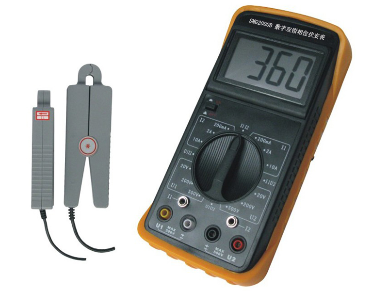
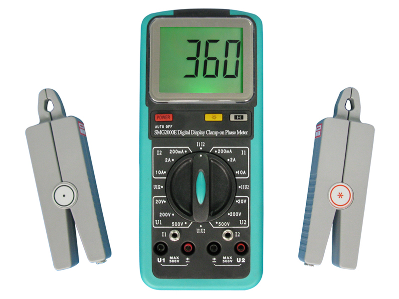
SMG2000E digital clamp-on phase meter is designed for the field measurement of voltage, current and phase, it is a measuring instrument with high precision, low-cost, portable hand-held and dual-channel input.
It can be easily measured the phase between U-U, I-I and U-I, distinguished the phase sequence of inductive/ capacitive circuit and three-phase voltage, detected the wiring group of transformer, tested the secondary circuit and bus differential protection system, read out the phase relationship between each group CT of differential protection, check the meter wiring is correct or not and so on.


Overview
(2) When measuring the phase between U1 - U2 because the two input circuit is completely insulated so it completely avoids the short-circuit caused by possible false wiring which resulting in the burning of the measuring instrument.
(3) The display adopts a high contrast LCD display the font is up to 25mm the screen angle can be freely converted about 70 degrees to get the best visual effects.
(4) Instrument shell is made of engineering insulating material comes with rubber and anti-vibration protective sleeve safe and reliable.
(2) Humidity: (20~80)% RH
(3) Wave forms of measured signal: sine wave β=0.05
(4) Frequency of measured signal: (50±0.5)Hz
(5) Position of Measured current carrying conductor in the nipper jaw: optional.
(6) Amplitude range of measured signal when measuring phase
Phase U1-U2: 30V~500V
Phase I1-I2: 10mA~10.00A
Phase U1-I2 or I1-U2: 10V~500V 10mA~10.00A
(7) External reference frequency electromagnetic interference: should be avoided
(2) Sampling rate: 3 times/ seconds
(3) Power supply: single laminated batteries with 9V the current of power supply is less than 5 mA.
(4) Dimension:
The size of the shell of meter: 186mm×86mm×33mm
The size of the shell of clamp: 140mm×40mm×19mm
The size of jaws: Φ7mm×8mm
(5) Weight:
The weight of meter: 280g
The weight of clamp: 2×200g
(6) The conditions of storage: temperature: -10℃~ 50℃
Models
3.1 Intrinsic Error
3.1.1 Reference Operating Conditions
(1) Temperature: (23±5) ℃
(2) Humidity: (45~75) % RH
(3) Wave forms of measured signal: sine wave β=0.02
(4) Frequency of measured signal: (50±0.2) Hz
(5) Position of Measured current carrying conductor in the nipper jaw: Optional position
(6) Amplitude range of measured signal when measuring phase: 100~220V 0.5A~1.5A
(7) External reference frequency electromagnetic interference: Should be avoided
3.2 The limits of intrinsic error
(1) AC Voltage (shown as table 1)
| Table 1 Error of AC Voltage | ||
| Measure range | Resolution | Intrinsic limits of error |
| 20V | 0.01V | ± (0.3% reading + 0.2% range) |
| 200V | 0.1V | ± (0.3% reading + 0.2% range) |
| 500V | 1V | ± (0.3% reading + 0.2% range) |
Input impedance: all the measure range is 2MΩ;
When measuring phase the input impedance of voltage terminal > 500KΩ.
(2) AC current (shown as table 2)
| Table 2 Error of AC Current | ||
| Measure range | Resolution | limits of intrinsic error |
| 200mA | 0.1mA | ± (0.3% reading + 0.2% range) |
| 2A | 1mA | |
| 10A | 10mA | |
(3) Phase: U-U U-I I-I (shown as Table 3)
| Table 3 Error of power-frequency phase | ||
| Range | Resolution | limits of intrinsic error |
| 0~360° | 1° | ±2° |
When measuring the phase of U1-U2 impedance of input voltage loop is 40KΩ.