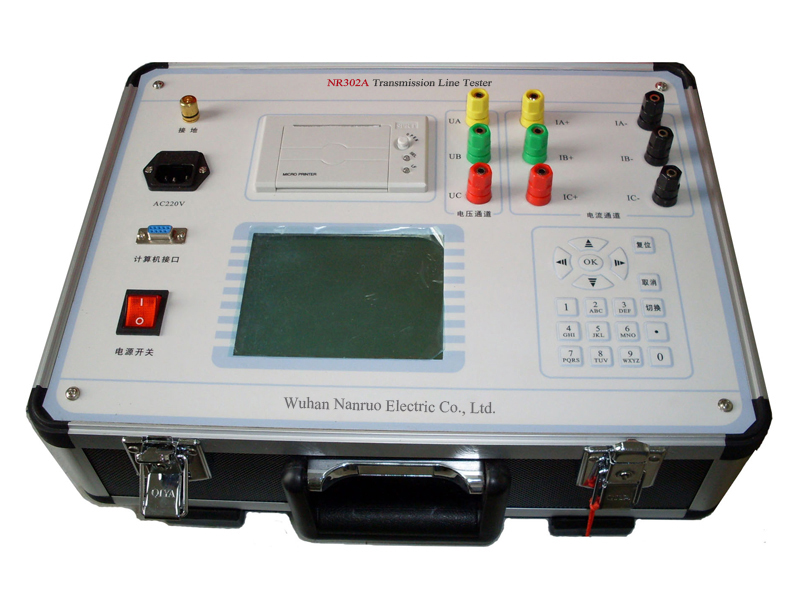
The NR302A transmission line tester is specially used for testing transformer loss parameters and line power frequency parameters. The instrument is designed with exquisite design, superior performance and powerful functions. It adopts advanced multi-A/D synchronous AC sampling and digital signal processing technology inside, which successfully solves the problem of synchronous measurement and calculation of multi-channel signals. The instrument uses a large-screen LCD display, English menu prompts, simple operation, equipped with a high-speed thermal printer, and is designed with a storage function to facilitate data storage and printing. The instrument is small in size, light in weight, easy to carry, and extremely convenient to use on site, which greatly reduces the labor intensity of test personnel and improves work efficiency.
Overview
● Strong anti-interference ability can accurately measure under the condition of the ratio between power frequency signal and pilot frequency signal is 1:10.
● External wiring is simple only one time to access the lead of the line to complete all the line parameters measurements. Completely solve the problems of the existing test methods which cause cumbersome wiring switching procedure and the interference of stability and accuracy.
● The instrument with high speed single chip microcomputer as the core to achieve the integration of test power meter and calculation model make a truck of equipment concentrated into a single instrument.
● The instrument uses 320*240 large screen dot matrix LCD operated with the rotating mouse imported from United States embedded mini-printer to print the results the operation is very simple.
● Instrument testing process is fast automatically complete test mode control boost-buck control data measurement and calculation and print measurement results one minute to complete a parameter measurement the test time is shortened the workload is greatly reduced.
● High accuracy measurement the instrument itself provides three groups of pilot frequency power supply (45Hz/57.5Hz 45Hz/55Hz 47.5Hz/55Hz) which is close to power frequency it can easily separate frequency and clutter effectively achieve high-precision measurement of small signals.
Models
| Voltage measurement range | AC: 25V ~ 500V | ||
| Current measurement range | AC 0.025A ~ 50A | ||
| Maximum output current | 10A | ||
| Output signal frequency | 45H/55Hz; 47.5H/52.5Hz; Interference current <40A | ||
| Measurement accuracy | Voltage current impedance | Power | |
| 0.2% |
When the power factor is > 0.1: 0.5%; When the power factor is ≤ 0.1: 1%; |
||
| Measurement range | 0.1-50μF | 0.5-400Ω | 0°- 360° |
| Measurement resolution | 0.01μF | 0.01Ω | 0.01° |
| 0.1μF-1μF: ±3% ±0.05μF | 0Ω-1Ω: ±3% ±0.05Ω | ±0.2° (voltage > 1.0V) | |
| 1μF-50μF: ±1.5% ±0.03μF | 1Ω-400Ω: ±1.5% ±0.03Ω | ±0.3° (voltage 0.2V-1.0V) | |
| Dimension | 535mm×435mm×360mm (not include wheels) | ||
| Weight | 61Kg | ||
Interference voltage: after connecting to the power supply of the instrument the longitudinal induction voltage is less than 350V;
Interference current: when the both end of the line is grounding it is less than 40A;
It can complete the test stably and accurately when the ratio between instrument output signal and interference signal is 1:10.
(2) Operating environment
Temperature: -15℃ ~ 40℃
Related humidity: < 90%.


